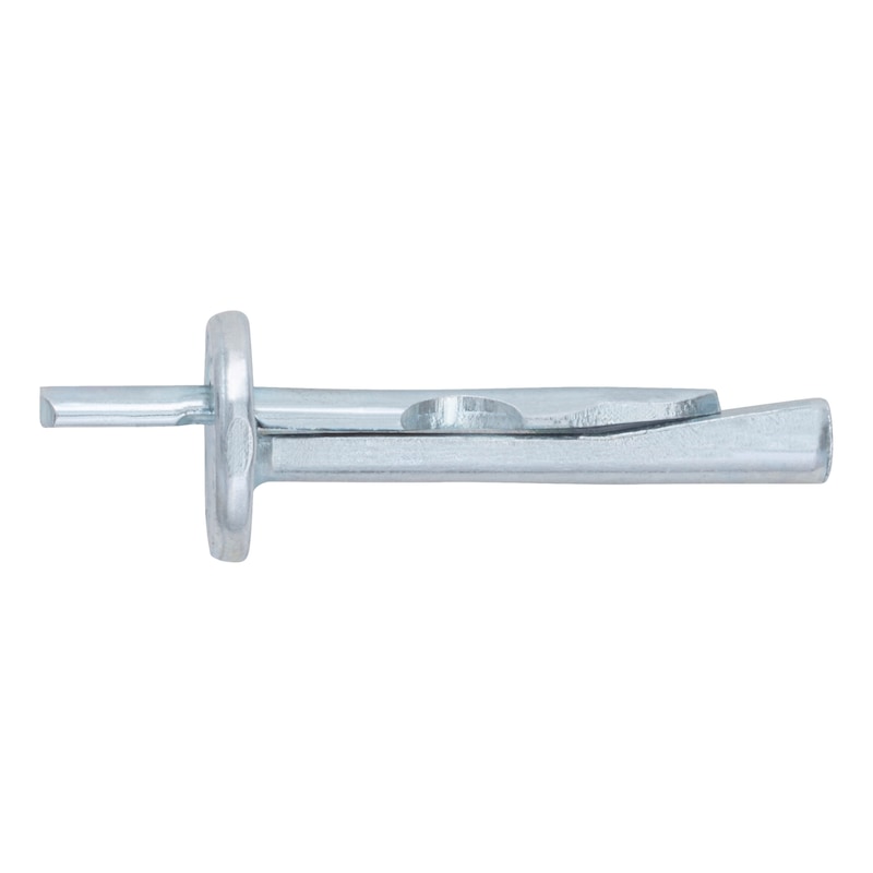
W-DN 2 ceiling nail
Ceiling nail W-DN 2
ANC-(W-DN 2)-(A2K)-5-6X40
Art.-no. 0905366640
EAN 4099618288890


Register now and access more than 43,000 products
- For efficient push-through installation
- Low drilling effort due to small drill hole depth and small drill hole diameter
- No additional drill hole cleaning necessary - three-factor ventilation of the drill bit is sufficient
- No additional drill hole cleaning is necessary when using the Würth dust extraction drill bit
- Easy insertion: Knock in the protruding pin with a hammer until flush
- Can be loaded immediately - no need to wait
- No special drilling or setting tools required
- Reliable and proven anchorage via friction locking - displacement-controlled expansion anchors
European Technical Assessment ETA-23/0659:
Anchors in a redundant non-structural system in accordance with EN 1992-4:2018, cracked and uncracked concrete:
- Static or quasi-static action
- Fire resistance R30 to R120
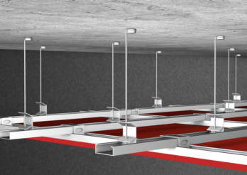
 Suspended ceilings


European Technical Assessment ETA-23/0659:
Anchors in a redundant non-structural system in accordance with EN 1992-4:2018, cracked and uncracked concrete:
- Static or quasi-static action
- Fire resistance R30 to R120
Datasheets(X)
Anchors in a redundant non-structural system with approval/assessment in accordance with EN 1992-4:2018 in concrete
- In normal weight concrete C20/25 to C50/60 (cracked and uncracked concrete)
- Fastenings subject to exposure to fire
For fastening lightweight fixtures
- Lightweight ceiling cladding and suspended ceilings, metal profiles, punched strips, wire hangers, vernier hangers, wooden battens, wooden slats, squared timbers etc.
W-DN 2 (zinc-plated steel) may only be used in dry indoor conditions.
Easy installation: Insert, knock it in flush, and done!
 | |
Type description | W-DN |
Material | Steel |
Surface | Zinc plated |
Anchor diameter | 6 mm |
Anchor length (l) | 40 mm |
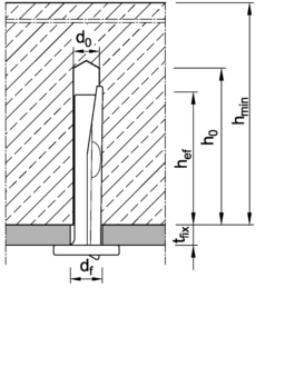
Max. attachment height (t fix) | 5 mm |
Effective anchoring depth (h ef) | 32 mm |
Nominal drill-bit diameter (d 0) | 6 mm |
Drill hole depth (h 0) | 40 mm |
Through-hole in the component to be connected (d f) | 7 mm |
Drill cutting diameter (d cut) | 6.4 mm |
Suitable for use in the following materials | Concrete |
Head type | Flat head |
Minimum component thickness (h min) | 80 mm |
| Performance data in concrete - anchors in a redundant non-structural system 1) in accordance with ETA-23/0659 | |||
| Anchor size [mm] | 6 | ||
| Effective anchorage depth | hef [mm] | 32 | |
| All load directions Admissible load at every angle Individual anchor without influence of the edge distance | Concrete C20/25 to C50/60 s ≥ 3 hef c ≥ 1.5 hef) | Fadm [kN] 1) | 2,4 |
| Admissible bending moment | Madm [Nm] 1) | 2,9 | |
| For admissible load when exposed to fire (R30, R60, R90, R120), please refer to European Technical Assessment ETA-23/0659 | |||
| 1) For statically indeterminate, redundant, non-load-bearing systems (anchors in a redundant non-structural system) in accordance with EN 1992-4. The partial safety factors of the resistances γM regulated in the approval/assessment and a partial safety factor of the actions of γF = 1.4 have been taken into account. For information on combining tensile and shear loads, on axial influence and the influence of the edge distance and on anchor groups, please refer to the appropriate guidelines, e.g. DIN EN 1992-4. The admissible loads per fixing point can be found in the corresponding national regulations of the EOTA member states. These may be lower than the admissible load of an individual anchor. | |||
| Installation parameters in concrete | ||
| Anchor size [mm] | 6 | |
| Effective anchorage depth | hef [mm] | 32 |
| Minimum spacing | smin [mm] | 200 |
| Minimum edge distance | cmin [mm] | 150 |
| Minimum member thickness | hmin [mm] | 80 |
| Nominal drill diameter | d0 [mm] | 6 |
| Diameter of cutting edges | dcut ≤ [mm] | 6,40 |
| Drill hole depth | h0 ≥ [mm] | 40 |
| Through hole in the member being connected | df ≤ [mm] | 7 |
| Head diameter | dh [mm] | 15 |
Select RAL-colour code
!! NOTE: On-screen visualisation of the colour differs from real colour shade!!


